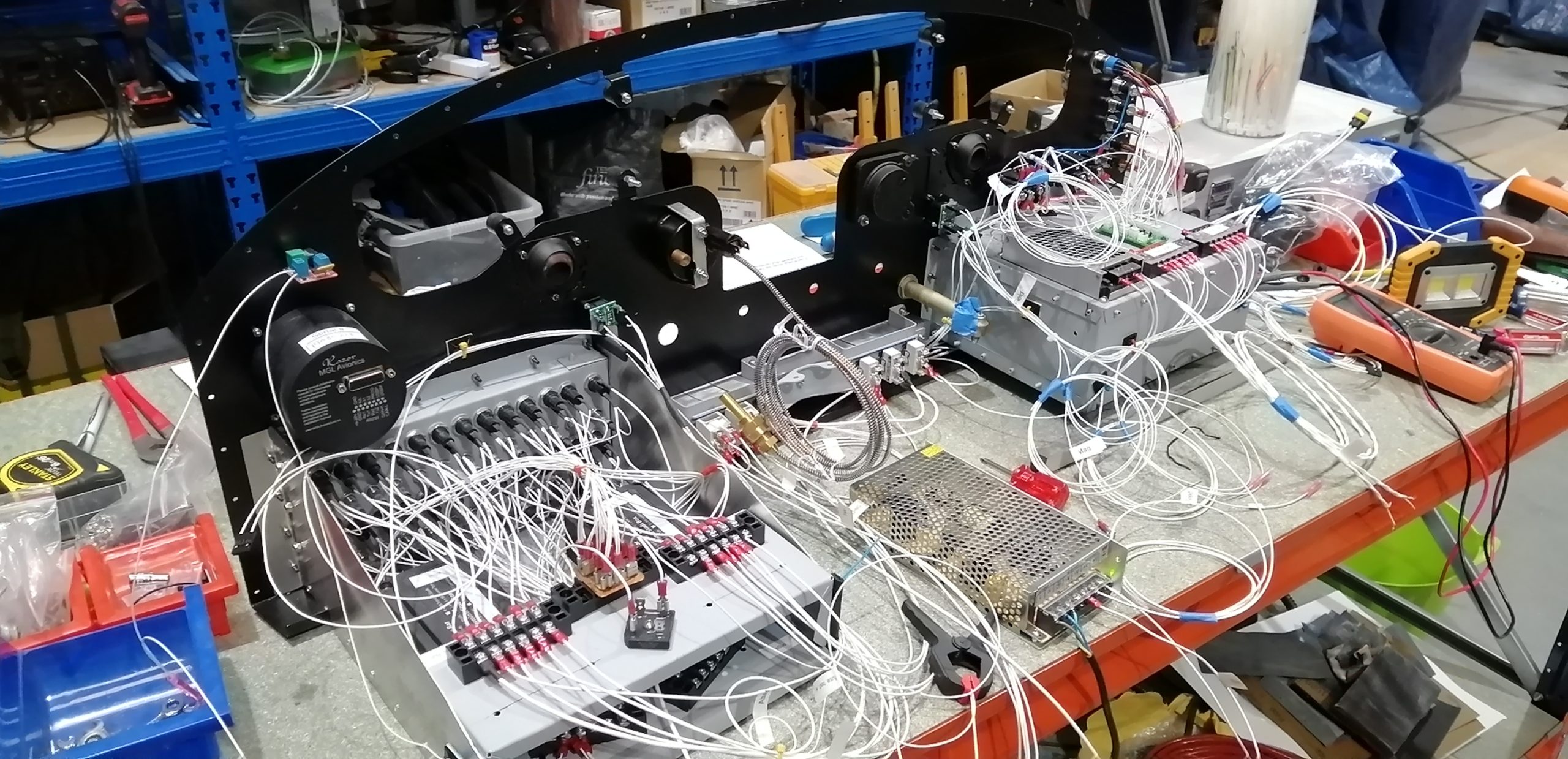
I gave up on logging hours. As I don’t have a 51% requirement, it’s a renovation not a kit build, there is no regulatory need to show amateur effort percentage. Of course, other than the engine rebuild, it’s 100% my effort anyway.
Panel completed
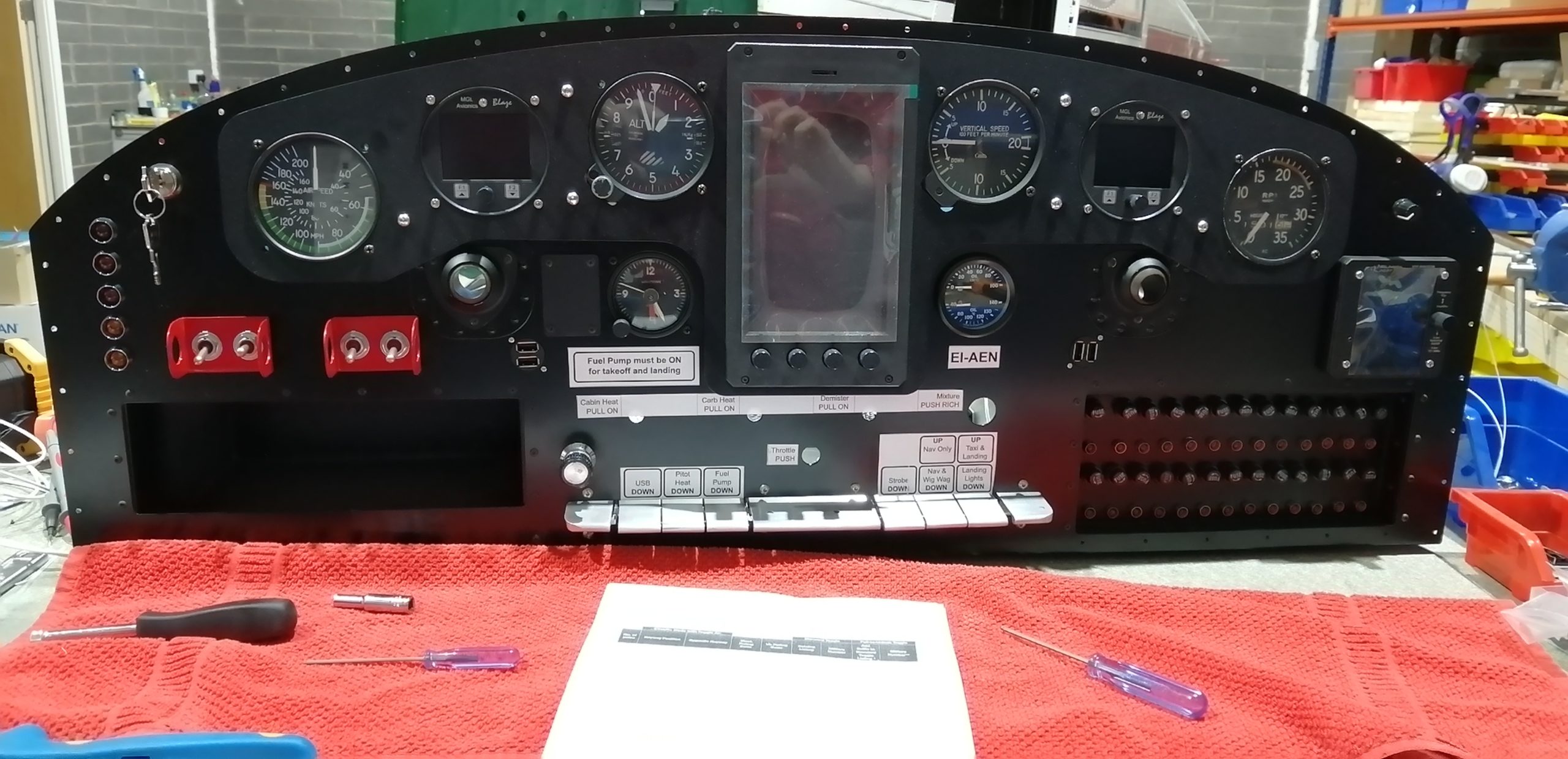
The panel is ready for installation. All its bits and pieces are installed, the instrument harness and pitot static tubing are all connected up.
Electrical system wired up to switches
The electrical system is based on a Bob Nuckolls design. Unlike the traditional Cessna master and avionics-master, it had two separate buses with no single point of failure. This is achieved by having a separately switched cross-feed from the battery to the “Essential Bus” and the traditional contactor-driven master switch sends power to the “Main Bus”. There is a feed from the main to the essential bus through a diode that prevents back feed from the eBus to the main bus.
All that sounds more complicated than it really is. In practice the critical (or essential) systems run off the eBus and everything else off the main bus. In the event of an alternator failure you switch off the master: that’s it. This leaves only the cross-feed connected to the battery, thus all your heavy loads are off and the critical stuff is on. The endurance on eBus only with an Odyssey PC680 is over 4 hours which is similar to the fuel endurance of the aircraft.
The idea here is instead of dead alternator = land immediately (pan pan, I have 20 mins to dead battery) it becomes: continue to destination / appropriate airfield, switch on the master when on approach and land as normal. To achieve this endurance every incandescent bulb has been replaced with LEDs and the only real current hog is the pitot heater.
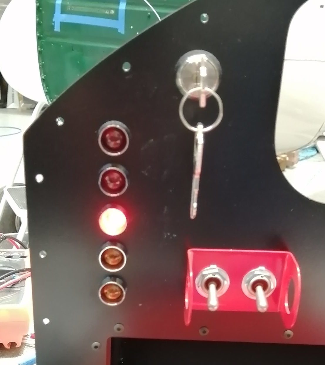
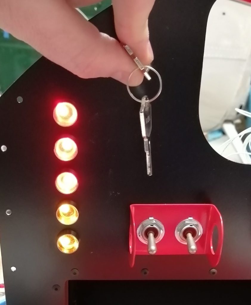
Annunciator wired and tested
How then do I know the alternator bit the dirt? What if the cross-feed isn’t turned on?
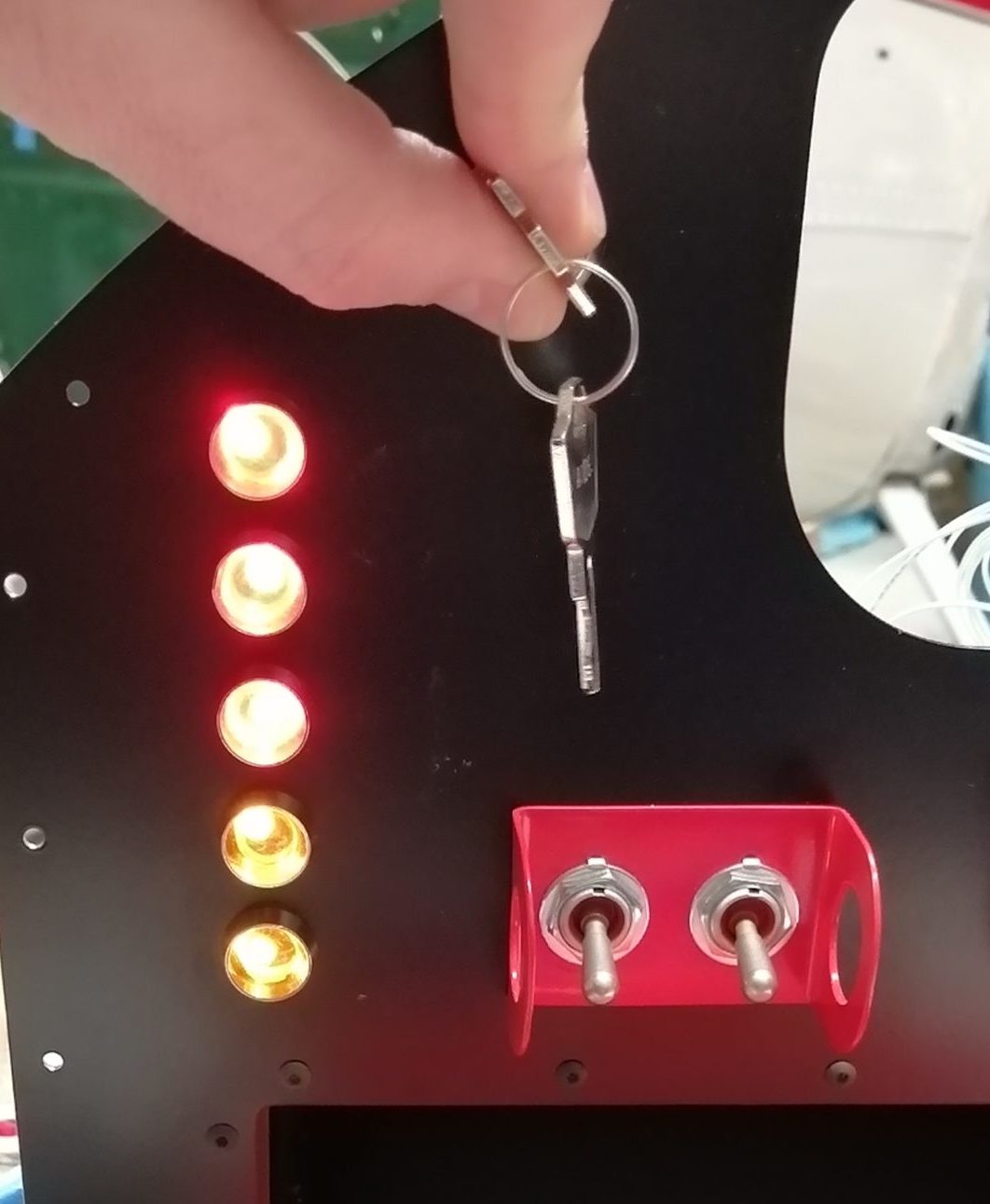
It started out in the schematic drawings as a couple of warning lights and ended up with these five. It was fairly straightforward until I realized that three of them are activated by a +ve signal and the other two -ve. That means the three have no voltage until the switch is on, the other two have voltage always but should only be lit when the ground connection is made by the failed device.
The warnings and cautions are like this:
- Alternator OFF (Red)
- Pitot Heat FAIL (Red)
- eBus Feed OFF (Red)
- Starter ON (Amber)
- Fuel Pump ON (Amber)
Once all that was wired up (on paper) I came to the conclusion that I need to be able to check that the lamp itself is working during preflight. While they are LEDs and should last nearly indefinitely the circuit might fail somewhere, better to know. I also needed a push-button for start as I’m not using the Off-Left-Right-Both-Start key switch; mostly because the one that was in it is in rough shape and I’m too cheap to buy a new one. The key-switch I used from a reputable UK manufacturer is intended as an industrial panel lock out switch and was 20% of the price of the aviation one. The mags are on a pair of toggle switches just because. It has three positions – centre is off, left momentary (springs back to the middle) is for test and right momentary powers the starter contactor.
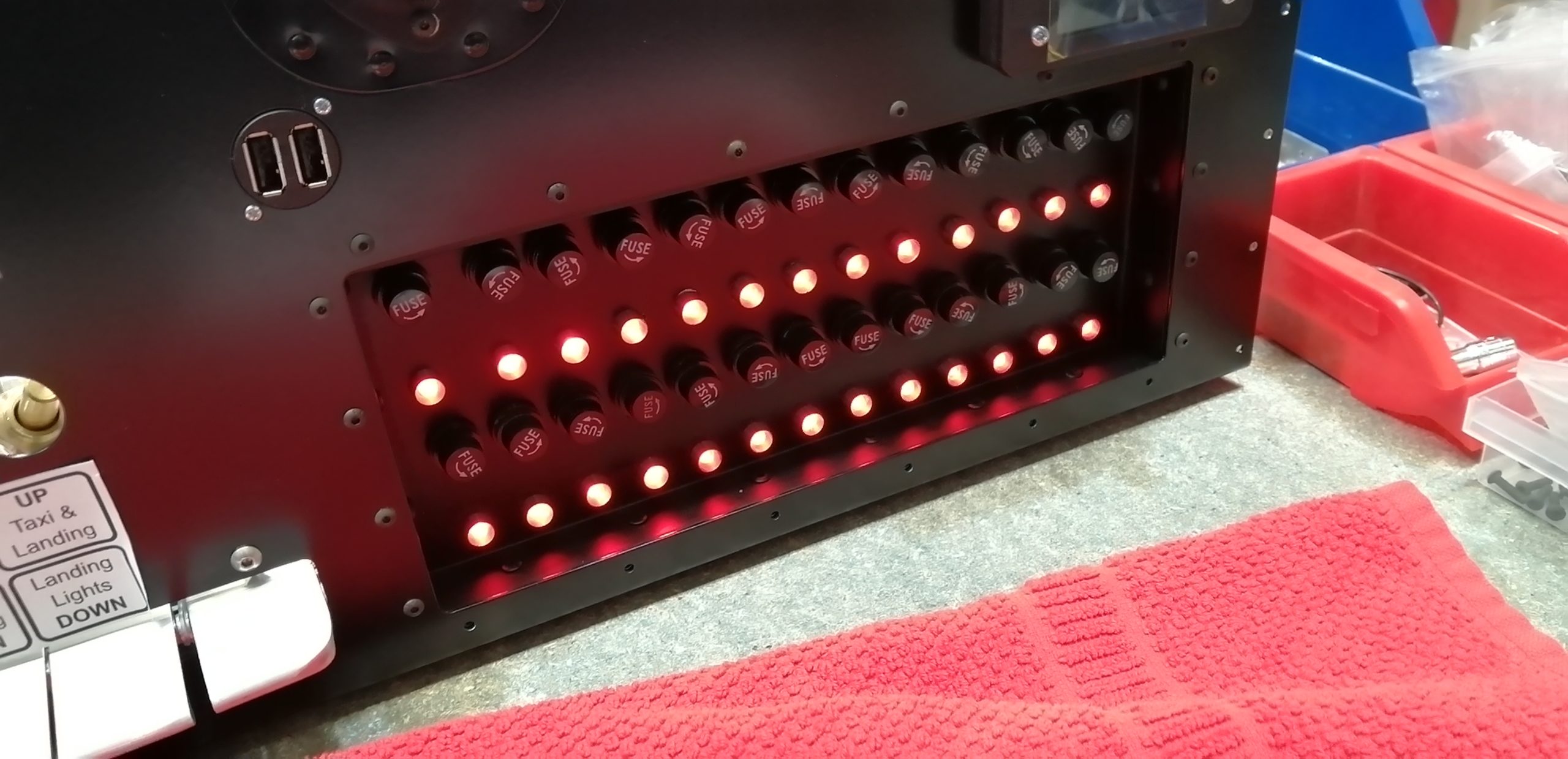
The test position lights the lamps and grounds all the test LEDs on the fuse panel showing if any of the fuses are dead.
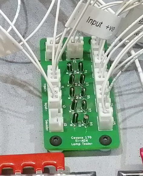
So far so good. The problem I discovered as I was wiring it up was that when I powered up the test circuit to make all the annunciator LEDs come on it would then connect power to the +ve signal devices so the fuel pump, starter contactor and eBus would get power via the 22gauge test circuit: not the plan.
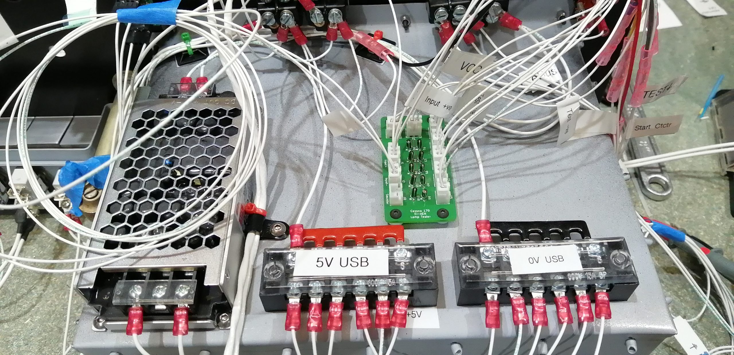
The result was a set of diodes. I found a couple of circuit diagrams of “common cathode” and “common anode” lamp test modules online which it turns out equate to the +ve and -ve signals mentioned about above. I used KiCAD (open source electronic CAD package) to magic up a PCB and uploaded it to aisler.net and along came the solution.
This allows the key switched lamp test to work and made wiring up the annunciator lights, signals etc. much easier.
Wired for pitot heat
With the addition of 12AWG aircraft wire the supply to the main bus and the wiring for pitot heat is in. I put an IP67 rated automotive disconnect at the wing root as with everything else that routes into the wings. That should make the wing installation literally plug and play.
USB Charging
With everyone using tablets and phones in flight these days there is always a need to plug them in. There will be no smoking, so no need for the cigar lighter socket with a converter jammed in and wires all over. I was unwilling to use the expensive certified charging sockets, especially as I wanted 5 charging points. The result is a “transport category” isolated DC-DC converter that turns 12V into 5V which in turn is fed to simple USB sockets.
This is all run through a single piano key, so the whole USB charging system can be shut off.
Ready to install
The picture shows why I gave up logging hours. The panel is relatively simple from the front despite its capabilities. I wanted it to look sort of period, the purists will of course object to any kind of glass, while having the capabilities and safety of modern avionics especially solid state AHRS. The complexity is all behind the scenes.
The panel is now tested and almost ready to go into the aircraft. I intend to add a door on the fuse panel to look a bit like the glovebox on the original. Once the new heating ducts are bolted in I will install and connect up the panel.
Work Date: 23rd September 2020
Hours: 100
Aircraft Section: Panel

